|
A GANG OF ELK |
 |
|
|
|
If you are out
in the wild and encounter more than one Elk, the correct term is gang
(herd can be used interchangeably).
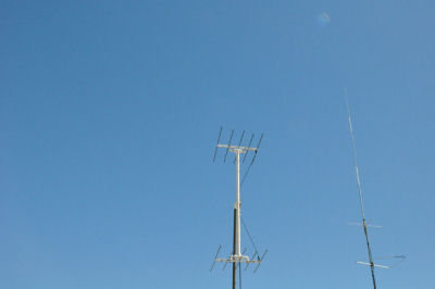
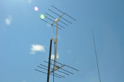
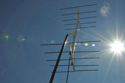
I guess in
amateur radio I should call them stacked. So what we have here are stacked
Elks.
This is one of
those want to do projects that just seemed like a good thing at the
time. The premise is to have something semi portable with decent gain and
be dual band.
One of the
products that ELK Antennas make is the 2M/440L5. This is a 5 element log
periodic dipole array (LPDA) designed to be lightweight, portable, and
cover the 2 meter and 70 centimeter bands. This antenna is primarily
designed as a handheld antenna for satellite work. Specs on the ELK
include 6.6 dbd gain on 2m and 7.0 dbd on 70cm. Front to back ratio is 20+
db. The antenna has a 24 boom and easy to remove threaded elements. Power
rating is 200 watts on 2m and 100 watts on 70cm.
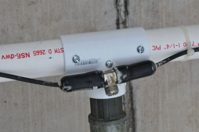
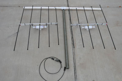
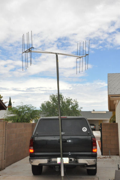
Pic of ELK with
my homebrew heavy mount. The heavy mount is standard PVC and adapts the ½
PVC that comes supplied with the antenna to 1 ¼ PVC to mate to my
homebrew stacking boom: |
 |
|
|
|
|
|
|
|
|
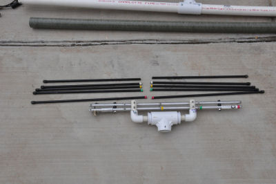
Pic of mount showing hardware placement for quick
disassembly. Parts are 2x ½ PVC 90 degree elbows, 1x 1 ¼ PVC T, 2x 1
¼ to ½ PVC reducers, 1x 10/32 x 2 ½ bolts and 2x 10-32 x 1 ½ bolts
with wingnuts. Double this list to do both antennas. |
|
|
 |
 |
|
|
|
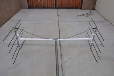
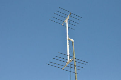
I had a
Cushcraft PD-2 on the shelf so that became the harness. The PD-2 provides
for stacking distance on 2m of about 69 inches. LPDA antennas have hot driven booms and must be insulated
from the mounting mast and need to have the feedline run 90 degrees from
the boom for a distance to help with matching. I was going to make a small
mount to run the feedline at 90 degrees, but settled for approximately 45
degrees for mechanical simplicity.
|
|
|
|
|
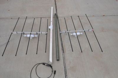
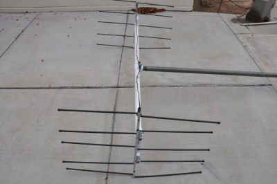
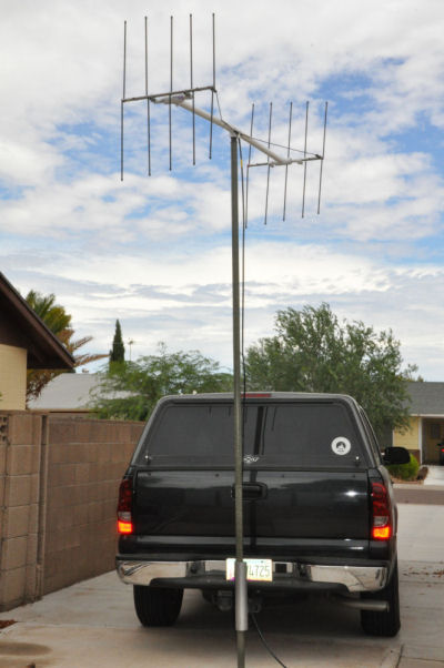
Pic of the
harness attached to both antennas and zip tied to the stacking boom. |
Pic of the stacking boom which consists of 2 pieces of 1 ¼
PVC with a 1 ¼ PVC T in the center. |
|
|
|
|
|
 |
 |
|
|
|
|
|
|
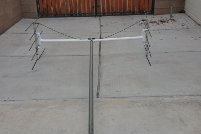
Close up of the stacking boom center. There is 1x 10-32 x 2
½ bolt/wingnut for each boom half and 2x 10-32 x 2 ½ bolt/wingnut for
the mast mount. The mast is made from fiberglass military tubes that are
commonly available. The military tubes slide all of the way into the 1 ¼
PVC T. These tubes are 4 long and have a 4 swage to allow multiple tubes
to slide together. (These are great thick wall tubes that have many uses
around the antenna farm). |
|
|
|
|
|
 |
|
|
|
|
|
|
|
|
Further pics: |
|
|
|
|
|
|
|
|
 |
|
 |
|
|
|
|
 |
|
 |
|
|
|
|
 |
|
 |
|
|
|
|
 |
|
 |
|
|
|
|
 |
|
 |
|
|
|
|
 |
|
 |
|
|
|
|
 |
|
 |
|
|
|
|
 |
|
 |
|
|
|
|
 |
|
|
|
|
|
|
|
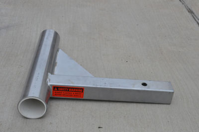
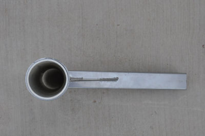
For enquiring
minds, this is an aluminum 2 hitch mount for flagpoles. It is 3 in
diameter with a PVC insert for an inside diameter of 2 ½.
|
|
|
|
|
 |
|
 |
|
|
|
|
 |
|
|
|
|
|
|
|
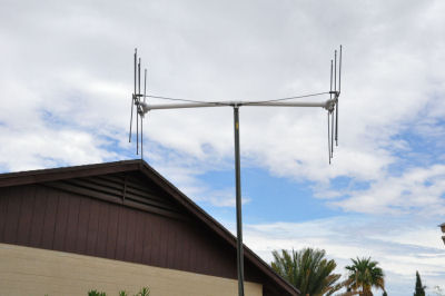
In absence of an antenna test range, the following SWR
readings were measured with an MFJ-269 antenna analyzer. Antenna was
mounted about 15 high, fed with 25 DX Engineering MAX400 coax to my wall
feed through, and then a 3 jumper of RG8X to the MFJ-269. |
|
|
|
|
| 144.0=2.0 |
432.0=1.2 |
440.0=1.7 |
457.5=1.1 |
| 144.5=1.9 |
432.5=1.2 |
440.5=1.7 |
417.0=1.1 |
| 145.0=1.7 |
433.0=1.3 |
441.0=1.6 |
|
| 145.5=1.6 |
433.5=1.3 |
441.5=1.6 |
|
| 146.0=1.4 |
434.0=1.4 |
442.0=1.5 |
|
| 146.5=1.3 |
434.5=1.4 |
442.5=1.4 |
|
| 147.0=1.2 |
435.0=1.5 |
443.0=1.3 |
|
| 147.5=1.1 |
435.5=1.5 |
443.5=1.3 |
|
| 148.0=1.0 |
436.0=1.6 |
444.0=1.2 |
|
| 148.5=1.1 |
436.5=1.6 |
444.5=1.2 |
|
| |
437.0=1.6 |
445.0=1.4 |
|
| |
437.5=1.7 |
445.5=1.5 |
|
| |
438.0=1.7 |
446.0=1.6 |
|
| |
438.5=1.7 |
446.5=1.7 |
|
| |
439.0=1.7 |
447.0=1.8 |
|
| |
439.5=1.7 |
447.5=1.9 |
|
| |
|
448.0=2.0 |
|
| |
|
448.5=2.1 |
|
| |
|
449.0=2.1 |
|
| |
|
449.5=2.2 |
|
| |
|
450.0=2.2 |
|
|
|
|
|
Anecdotal
performance: KF7MBI Armando assisted me with some testing. He is running a
Yaesu FT-2900R with a J Pole and his QTH is about 6 miles from me. Im
used an FT-857D. Both of us on 10 watts FM on 146.58.
Pointed directly
at him we registered S7 both ways.
Turned directly backside, I received him S4, he received me S5
When turned 90 degrees, I received him S3, he received me S4 |
|
|
|
I also tried a couple of repeaters that had some activity
on them.
|
|
|
|
|
|
Antenna pointed at/back/side
147.00=S9++/S8/S8
146.92=S9++/na/S8 |
Tucson area 70cm
444.875=S7/na/na
444.975=S9+/na/na |
|
|
|
|
|
To sum up, it
was an interesting project. I made the system more portable than needed
for my use as I have a 6.5 bed Silverado and can leave most of the system
together for transport. I do have plans to make an adapter so the antennas
can be run horizontally.
Disclaimer:
I have no financial or other interests in the companies/products named
herein. Opinions are my own.
Thank you to my
YL Dominique WD7DX for her assistance with this project, especially being
the rotor during testing.
Copyright
WB7X.net |
|
|
|
|